M2 Micron All Metal Extruder Upgrade
March 10, 2015 (posted 8-26-22)
 M2 Micron All Metal Extruder Upgrade
This is an old project I did back in 2015 and posted to the Makergear Forum but I’m recreating it here to save for myself encase I ever redo this project.
This is Micron’s All Metal Extruder Upgrade that I found on eBay. It’s not listed as a direct bolt on upgrade for the M2 but there’s pictures of it on an M2 so how hard could it be. It ran me $125 dollars to my door and took 22 days to get here from Israel. It might be a bit pricey seeing as it’s not an absolutely necessary upgrade but I like modifying things so we’ll see if it’s worth it. (note – It wasn’t)
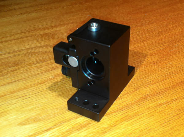
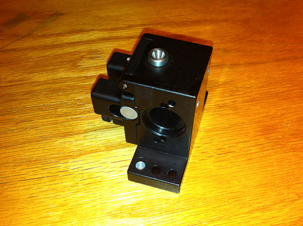
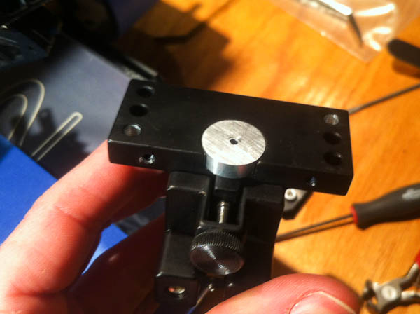
It’s milled from billet aluminum and is anodized black. My initial impressions are it is very well designed and the machining is top notch, there not a milling mark on this thing.
The bearing is spring loaded and flips up to help clear any feeding problems that may arise.
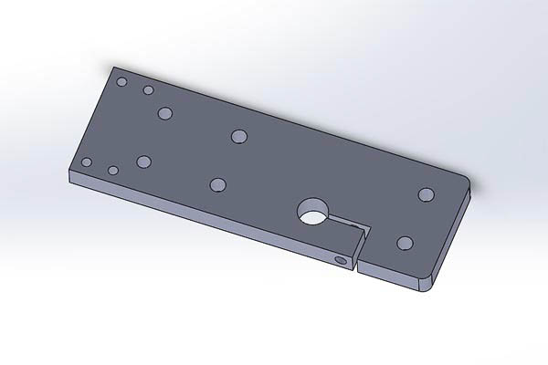
The eBay auction is only for the extruder itself so while waiting the 22 day for it to arrive I designed a new mount based off the new V4 hot end with some help of some dimensions that were listed on the auction page.
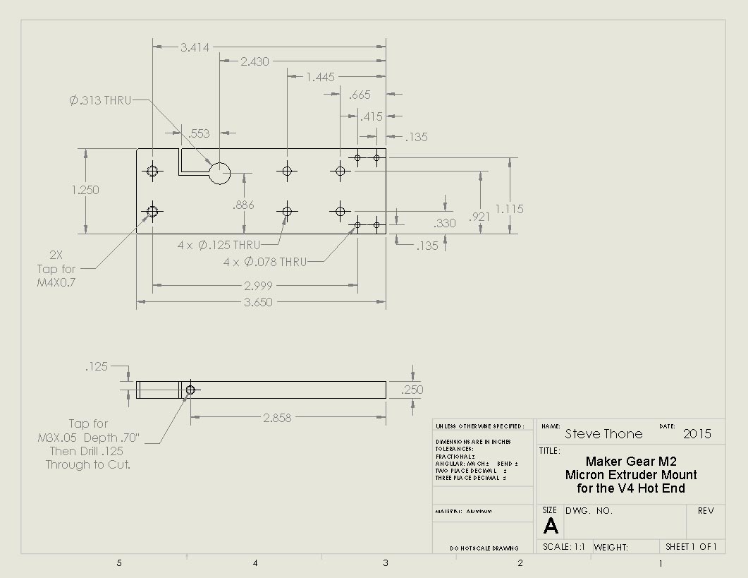
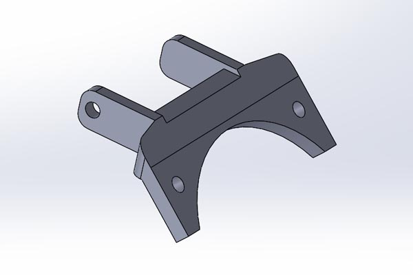
I don’t know if anyone will ever use this info but here’s the specs on the mount I made for the V4.
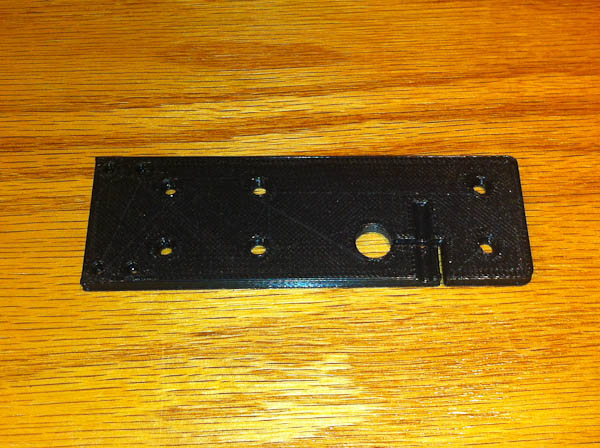
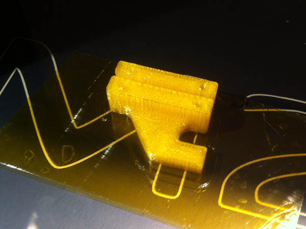
Before milling out a new mount I decided to print a prototype first to make sure my design is correct. Gotta love 3D printers, I only printed the prototype at half the thickness the mount will be.
It won’t have the separation between the mount and the actual hot end that the stock V4 setup has but you can still see the filament between the two, then again everything is metal now so it shouldn’t matter.
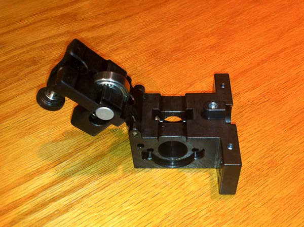
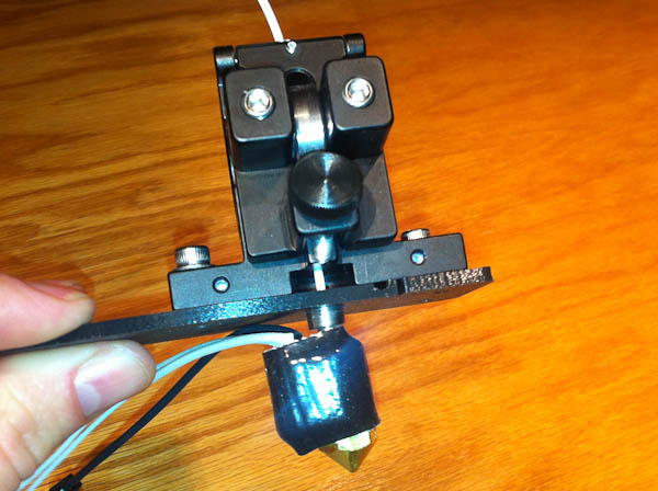
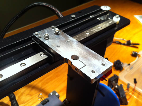
Here is a mock up of the new mount compared to the stock V4 one. It will hang out a little farther hopefully there won’t be any issues with the added 5oz of weight it adds to the slide.
While this thing is listed as not being directly for the M2 the bolt pattern is a perfect match width wise so it will bolt through the new mount right to the slide just like the stock one.
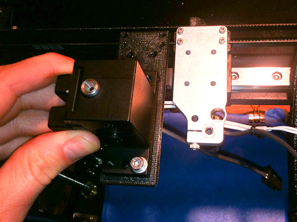
The motor mounts at an angle to the new extruder but bolts up fine, I may have to move the gear out a bit though.
I’ll have to design/print a quick L bracket to mount the fans to the extruder but that should be pretty easy.
Micron sent me a link to a guy who has all ready done one of these on his M2 and he was nice enough to give me a copy of his wire stay. (No point in reinventing the wheel here.) I’ll just have to drill and tap the extruder to mount this piece.
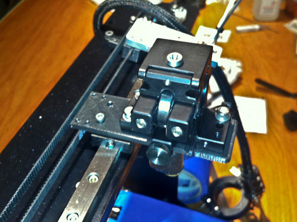
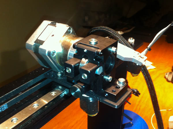
Finished up my mount today, if any one is interested the process I went through to make it a quick run down can be seen HERE. The way the motor mounts to the new extruder it puts the bearing on the other side so before I took my printer out of commission to mount this thing up and give it a try I needed to figure out how to tell S3D to reverse the extrude and retract commands. It turns out I just had to flip the wires (connector) on the stepper motor.
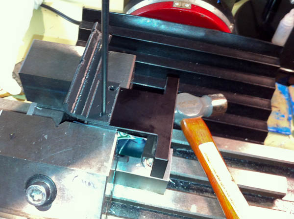
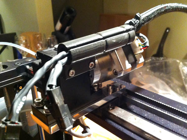
I had to make a few modifications to the actual extruder. Using a transfer punch I marked the two holes for the new cable box.
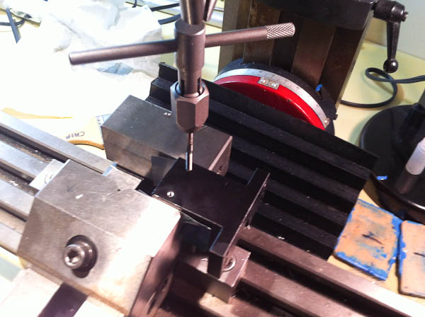
Then I drilled the holes to a depth of .365 using a #39 drill bit and taped them for a M3 x 12 screw.
I also had to drill out two (one front, one back) of the mounting holes in the extruder as two of them were tapped to fit a m4 screw.
The new mount bolts to the belt clamp with the same screws but, I switched to M3 x 12’s (with a few washers) to mount it to the X carriage. (M3 x 10’s would be a perfect fit I think.)
The extruder mounts with two M3 x 18 screw into the rear holes right to the X carriage, and two M4 x 12’s (that came with the extruder) to the holes a tapped in the new mount. (M4 x 14’s would be a better fit here.)
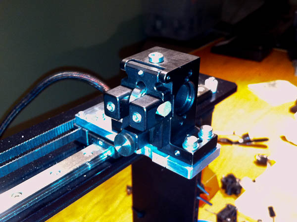
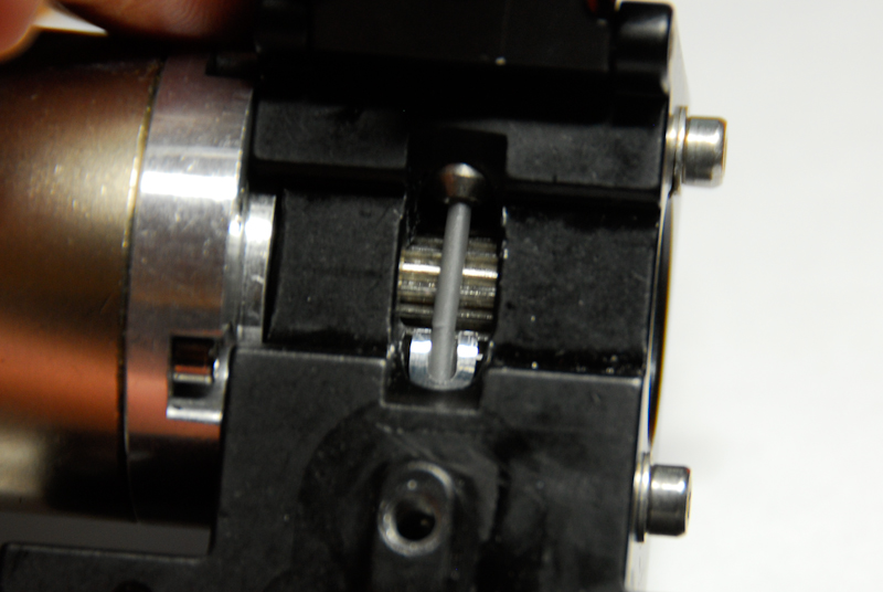
I had to move the gear out to be flush with the end of the shaft so it aligned better with the bearing in the extruder.
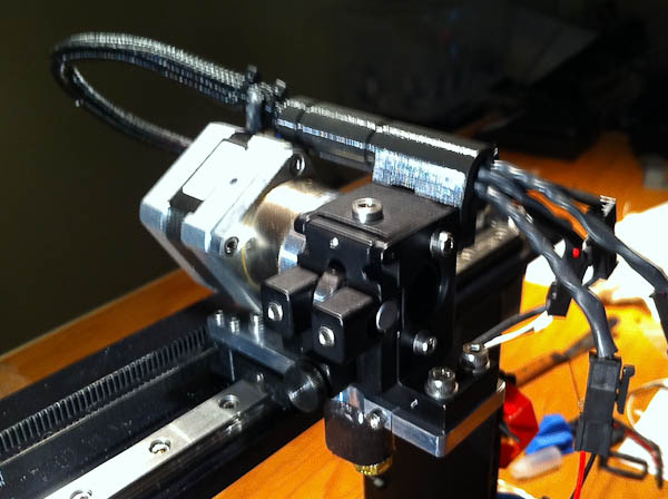
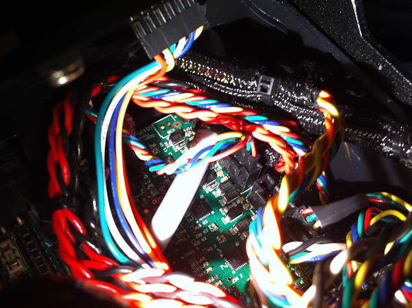
Here the motor has been mounted and the cable box installed. (sorry for the blurry pic.)
I cut the cable box a little shorter to leave slack in the fan wires until I figure out where they will mount. I may reprint it later on.
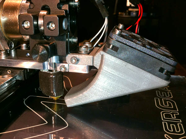
After switching the E0 plug around….
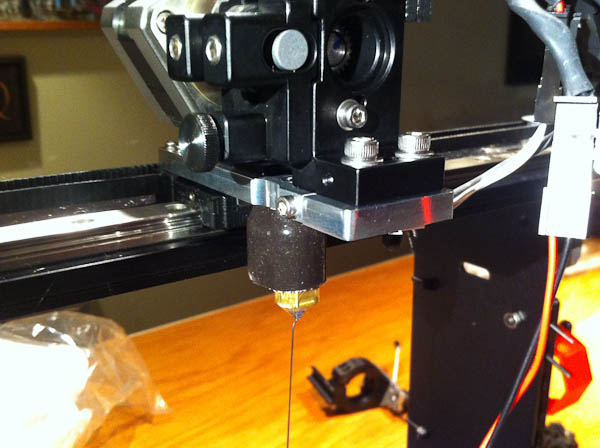
… I have extrusion.
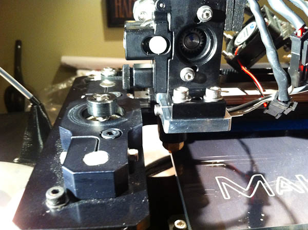
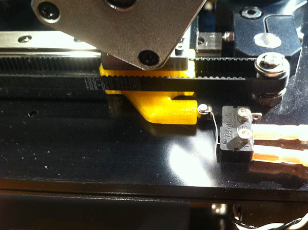
Besides making a new fan brackets I have to fix a few other issues. With the hot end just touching the edge of the glass in what should be the home position the stop on the belt clamp is to far away from the end stop switch to activate it so this will have to be redesigned and reprinted.
The extruder is a little bigger now with the door for the bearing and thumb screw so I will have to make a smaller Z knob also.
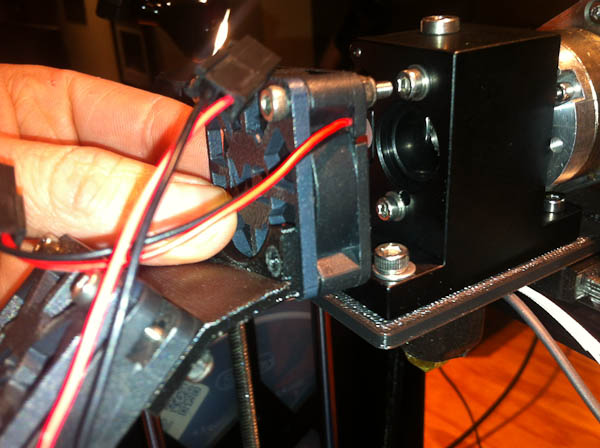
This is what I came up with for a fan bracket. I didn’t feel like taking the new extruder mount back off to drill holes in the front for a fan bracket so I just designed around one of the holes that were all ready on the side of the extruder. This will probably change anyway because I want to try one of those ducted fan shrouds because the fan seems a little far away from the hot end now.
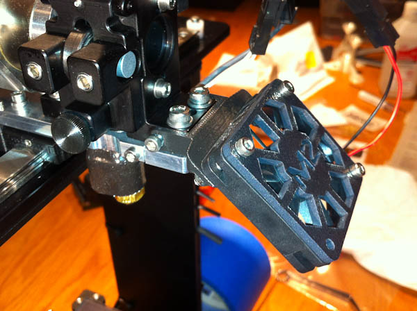
Here is the printed mount, I had to hold the fan by hand while I printed this one, glad it only took about 10 minutes to print.
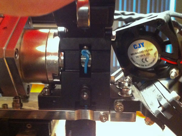
Things started to go down hill when I tried to print a new belt clamp with an extended striker. I decided to give ABS one more try because I wanted it to be strong but once again after a few layers it clogged and I had to stop printing. I tried switching spools of ABS but couldn’t get that to work either. As you can see from the above picture I started to have problems with the extruder too. I even tried switching to a PETG sample I had but I couldn’t get that to feed either.
The bottom of the extruder as a recess cut into it (which I think is meant for the V3B) and I think this is allowing the filament to bend and kink up.
I machined up a quick spacer to fill in the gap. After installing this though I still couldn’t get the PETG to feed as I think the nozzle is just too clogged.
It took all of a minute to change nozzles (love the V4 setup) after that I was able to print the belt clamp without any problems. (Yay! for my first PETG print too) I might not need that spacer after all but then again for flexiable stuff (like Ninja flex) it might be required, I’ll have to test that out next.
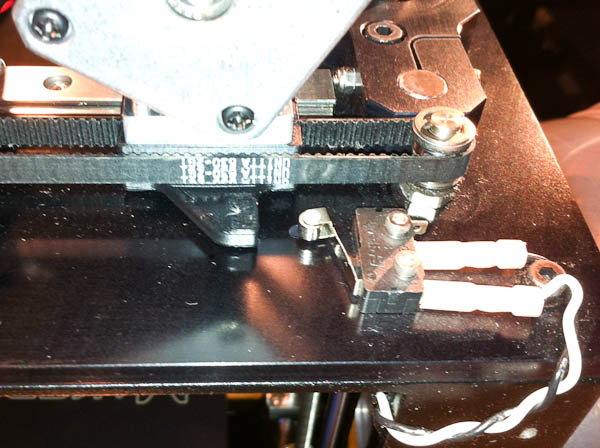
Here is the new Belt Clamp installed and it activates the end stop perfect now.
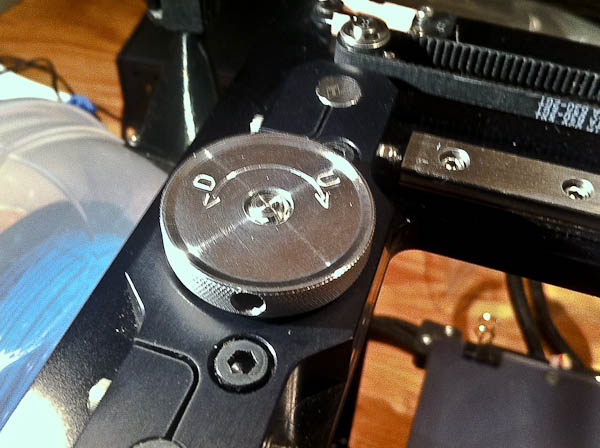
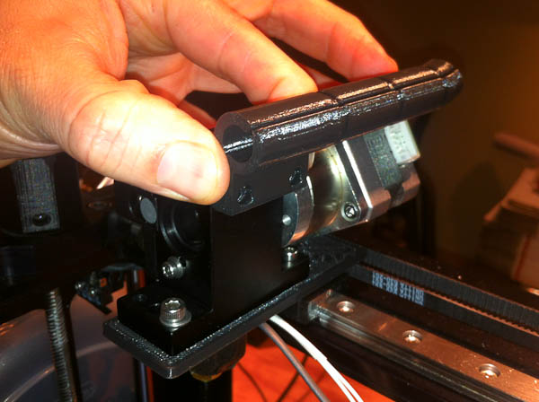
While I was on the lathe making the gap spacer I decide to make a new low profile Z Knob too to clear the thumb screw on the extruder door. I always forget which way is which so I marked it with Up and Down to make life easier.

Tried my hand at making a fan duct today. I was a little worried with the thin single point screw attachment so of the last mount so I made the mount separate this time and used a couple of neodymium magnets to hold the fan duct to this mount. This way if I happen to hit the fan it should flex and won’t just break the mount. I thought I might be able to remove it to use a quick mounting dial gauge too but I’m not sure if the little magnets would be strong enough for that purpose.
Here it is mounted to the new extruder. I’m not sure how well it will work yet but it looks pretty good so far. I took so advice and closed off the top of the shroud tip and I also angled the entire thing so it points directly at the hot end more, I think this version is going to work even better now.
I was interested mainly in this after having a few issues of cracking the printed type mounts. The spring loaded bearing and flip up door are a nice feature and I’ve had zero feed issues with PLA (that’s what I run the most) I don’t even make that little 45° cut on the filament anymore I just shove it in there and the stuff feeds straight through. With the flip up door I can even clean off the drive gear a bit at a time through the trap door which is nice.
Those good points being said…. I was also hopping to eliminate the problems of flexible filament wrapping around the extruder gear during printing… I tried it this weekend and well I couldn’t even get the flex stuff to feed through this extruder at all. The gap between the gear/bearing and the bottom feed hole of the extruder is just to larger and it just bunches up in the extruder.
After jamming this damn thing up one too many times I just decided to remove this thing and go back to the proven stock V4 setup. After removing it though and giving it a quick once over I think I can fix the problem pretty easy. (at least for easy for me anyway because I have the tooling ![]() )
)
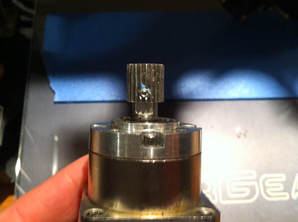
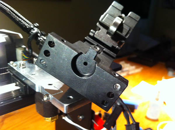
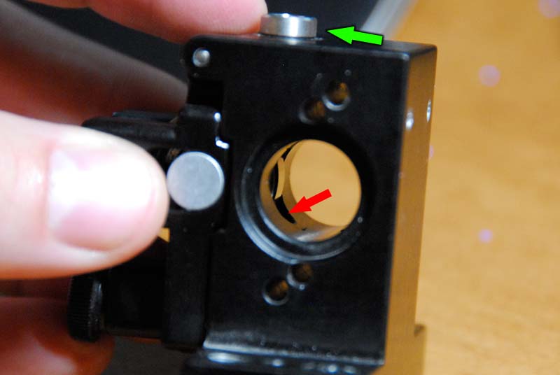
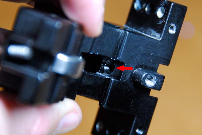
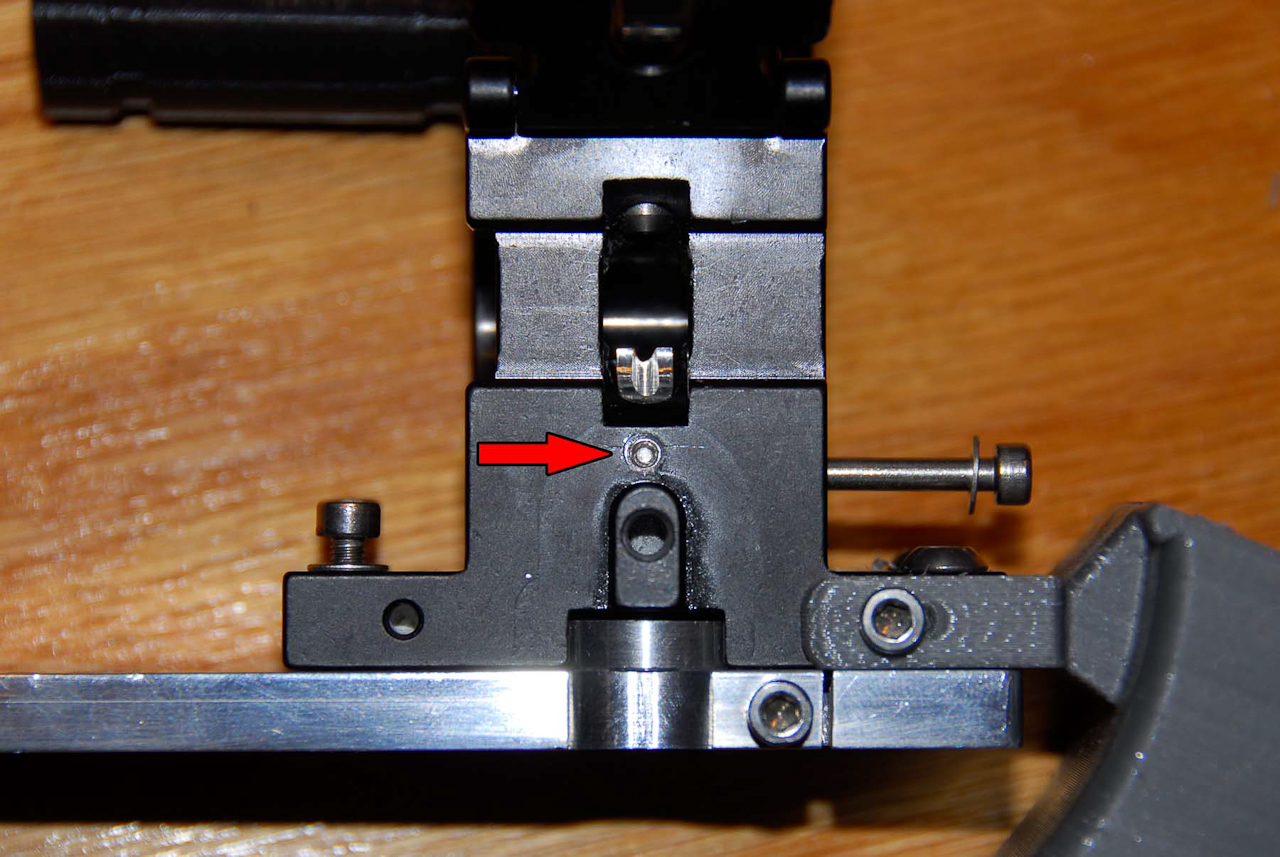
The problem with this extruder is the gap after where the filament leaves the gear and bearing is huge (red arrow) which causes the filament to just bunch up if it feeds to fast. (and by to fast I mean any speed.) Thinking of running any kind of flexible filament through something like that… well it’s just not going to work.
To compound the problem the beveled relief they put into the bottom just makes the problem even that much worse.
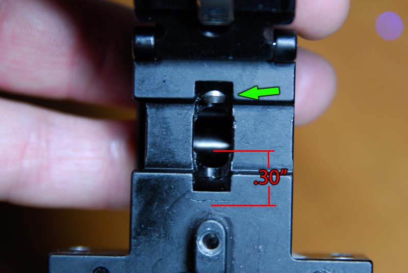
From where the filament leaves the drive gear to the bottom of that relief is about .30 of an inch. (like I said HUGE!)
I plan on drilling out the bottom of the extruder with a 3/16″ bit and then making an insert much like they have in the top (green arrow in pictures) I should be able to fit this insert close enough to the drive gear that it should take care of the jamming.
This is all in theory anyway, I’m either going to fix this thing or make it totally unusable (which it almost already is so no loss if I fail.)
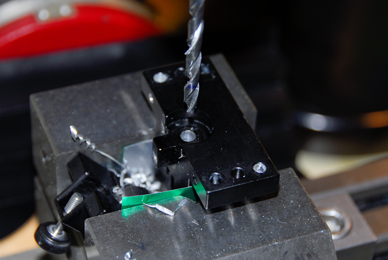
No going back now… I drilled the extruder out with a 3/16″ bit.
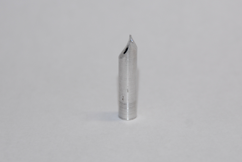
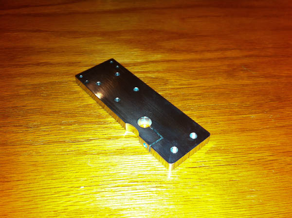
This is the quick prototype insert… I left little room for error with this thing.
It might need some more tweaks like rounding the edges so it doesn’t shave the filament but once it’s mounted in the extruder there shouldn’t be any way for that filament to bunch up now. I’m hoping a simple set screw will hold it in there for now. (still need to drill for that.)
Here’s where I put the set screw.
Overall this was a fun project and only took a few days/hours of work but in the end it wasn’t worth doing because it could only reliably (I use that work loosely) feed PLA. In the end I went back to the V4 stock setup.
All Information, Pictures, and Material is copyright © 2022 by Stephen Thone and may not be used for any personal or commercial purposes without the consent of the author. All rights reserved. The Author makes no guarantees or warranties as to the accuracy or completeness of, or results to be obtained from accessing and using the Information herein.